Roadway and vehicle evidence in rollover collisions
Reconstructing a rollover involves examining frequently observed physical evidence on the vehicle and the roadway
A traffic collision reconstruction utilizes information and data gathered from many sources. Sources of information include but are not limited to traffic reports, vehicle and scene photographs, statements and testimony. Additional sources may include vehicle specifications, scientific literature, and forensic testing. However, physical evidence is vital to the improved accuracy of a complete collision reconstruction.
Rollover collisions are a unique category of all automobile collision types. Other categories include intersection, rear-end or head-on collisions, collisions with fixed objects, or side impacts. Traffic collisions may also involve motorcycles, bicyclists, and pedestrians. With each category of collision, specific methods of interpreting and analyzing a unique set of physical evidence may be employed.
Reconstruction of rollover collisions generally begins at a point with known parameters, namely the point of rest (POR) where vehicle speed is zero and the vehicle location is defined. From that point, the reconstruction typically works backwards, analyzing the rollover sequence back to where it began. The investigator will then examine the events that precipitated the rollover sequence.
Physical evidence created at the onset and throughout the rollover sequence is used to characterize a rollover event. Collision parameters including but not limited to vehicle roll distance (i.e., the distance from trip to POR), vehicle trip speed, vehicle roll count, and vehicle roll rate during the sequence may be determined if the physical evidence is thoroughly and accurately documented and photographed. Preservation of physical evidence is important. Moreover, physical evidence does not improve with time, so commencing an inspection of the roadway or vehicle early in the analysis is the best practice to preserve what is available.
Law enforcement investigators often photograph the vehicle and any physical evidence they believe is relevant to a particular incident, especially in cases involving severe injuries and/or fatalities. Now more popular than ever before, investigators use Total Stations, Lidar or other measuring devices to accurately document the location of physical evidence.
This article examines frequently observed roadway and vehicle physical evidence and their specific role in the rollover collision reconstruction.
Roadway evidence
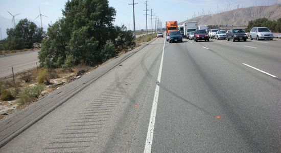
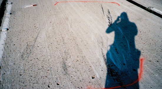
- Trip point – The trip point is the location where the vehicle begins to roll over, and is marked by an abrupt transition from one vehicle dynamic behavior to another. In the case of a vehicle in a yaw (rotation about a vertical axis when viewed from above), the vehicle is rotating/ sliding before it suddenly trips, i.e., the vehicle’s center of gravity moves beyond the leading tires, and the roll sequence begins.
The trip point illustrated in Photo 1 is distinct and uniquely identified by the termination of tire friction marks (marked with orange painted dots). When in a yaw, a vehicle creates tire friction marks along an arc. The path of individual tires determines the vehicle’s yaw angle (the included angle between the vehicle’s CG velocity vector and the vehicle longitudinal centerline).
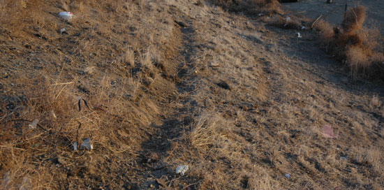
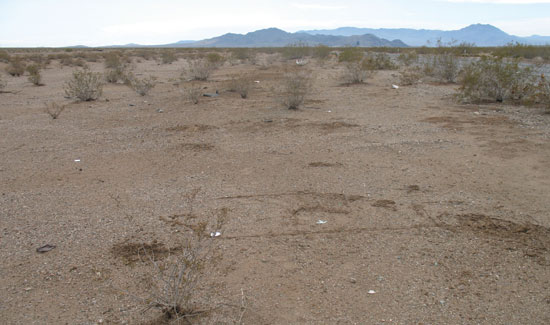
- Vehicles in a yaw – on dirt such as an unpaved shoulder or embankment often create furrows. Furrows are caused by the wheel/tire assembly with a sufficient yaw angle to plow the soil. Furrows often precipitate the trip point, observed in the foreground of Photo 2 (see page 96). These furrow marks were created when a light truck left the highway and traveled down a dirt embankment prior to rolling over.
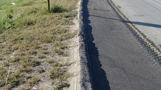
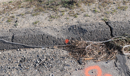
- Asphalt curbs – frequently associated with initiating a vehicle rollover. With a sufficient yaw angle, the wheel does not simply roll over the curb, but instead the curb becomes a tripping mechanism. Often, wheel strikes are evidenced by gouges to the asphalt or concrete, as shown in Photo 3 and Photo 4.
- Scrapes or gouge marks – Scrape or gouge marks are created by vehicle components interacting with the roadway. Scrapes may be considered linear and somewhat shallower, compared to gouges, and are caused by the vehicle exterior interacting with a road surface, shown in Photo 5 (under shadow). Gouges are characterized by a deeper artifact, with more road material removal. Scrapes or gouges soon after the collision are often denoted by their lighter appearance compared to the adjacent surface material. Scrapes tend to be longer near the start of the rollover trajectory by virtue of a higher linear velocity relative to the roadway. As linear velocity is reduced by friction with the road, the potential for longer scrapes is reduced. The location on the road, or the relative distance between groups of scrape marks, can assist in determining what portion of the vehicle created them.
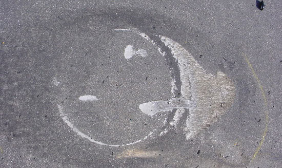
- Wheel impacts and gouges – Wheel impacts are a subset of gouge marks characterized by their crescent or circular shape, shown in Photo 6 (see page 101).
Wheel impacts also occur off the highway and reveal a circular shape, as shown in Photo 7. Identification of the wheel that created the artifact, i.e., left or right side, front or back, will depend on the location and orientation of the crescent relative to the roll direction and whether it is a driver side or passenger side leading rollover. Distinguishing between left and right side wheel impacts will help characterize the vehicle rollover dynamics.
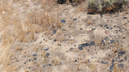
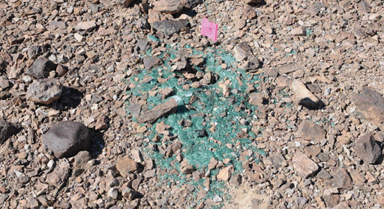
- Fractured glass – Fractured glass is often found along the vehicle’s roll path, shown in Photos 8 and 9. Vehicle window glass breaks due to impact forces or deformation to the vehicle’s structure. The thickness of these glass fragments can be measured with calipers, shown in Photos 10 and 11. The thickness, color and location of the glass fragments found can be cataloged. Comparing the glass fragments found at the collision site to those of the incident vehicle will help determine to which window the glass belongs, and more important, where in the rollover sequence the window fractured. Alternately, a suitable exemplar vehicle may be used when the incident vehicle is no longer available. Determination of the sequence of vehicle deformation sufficient to fracture window glass will help characterize vehicle orientation throughout the rollover sequence.
- Paint, plastic and rubber transfers – Paint transfers are caused when a painted portion of the vehicle contacts the roadway (black paint in Photo 5). A shallow scrape may be formed with a distinct color transfer corresponding to the exterior body color of the vehicle. Observing a paint transfer can assist in identifying the body panel and vehicle orientation at that location in the rollover sequence. Additionally, plastic transfers may occur when a plastic lens, trim piece, or side mirror contacts the road surface, as shown in Photo 12 (see page 104). Again, the position and color of a plastic transfer relative to other artifacts may assist in determining vehicle orientation when the plastic transfer was created. Rubber transfers mark the location where a tire contacts the road surface, as in Photo 13. Rubber tire transfers often reveal a striation pattern consistent with the tread belt or shoulder pattern.
- Vehicle point of rest – The point of rest marks the end of the rollover sequence. The vehicle may come to rest on its wheels, side, hood panel or roof. If photographs of the vehicle at the POR do not exist, then physical evidence at the collision site, such as paint marks identifying tire locations, an area of scorched asphalt from a vehicle fire, or divots in the dirt from impacting tires may help estimate it.
Vehicle evidence
- Scratches to vehicle exterior – Scratches to the vehicle exterior is evidence of contact between the vehicle and the roadway (asphalt or concrete), or the dirt and gravel shoulder, shown in Photo 14 (see page 104). Alignment of the scratches to the vehicle’s exterior can identify the vehicle’s orientation relative to its surface velocity vector. The orientation of vehicle scratches may change with each rotation such that the roll count may be identified by counting the sets of unique scratch angles. Consideration may be given to the complexity of the vehicle motion and the ground topography throughout the roll trajectory.
- Wheel/Tire assemblies – Wheel assembly impacts may be of sufficient force to deform the tire sidewall, allowing the outer wheel rim to contact the roadway. Evidence of rim contact are gouges and scrapes to the steel or alloy wheel. Many factors including, but not limited to wheel composition, tire inflation pressure, and impact force will affect the severity of artifacts observed. Oftentimes, scraping the roadway will cause a build-up of asphalt at the outer wheel rim, as shown in Photo 15 (see page 104). Sometimes, wheel impacts are of sufficient force to fracture the wheel, like Photo 16.
- Impressions – Impressions to the vehicle exterior may be unique depending on the object struck, but are not uncommon. When vehicles interact with an object of significant resilience (i.e., curb, tree, wall, etc.), a corresponding mark on the vehicle exterior may be created, as Photo 17 (see page 105) shows a tree impression. Photo 18 shows a concrete median barrier impression. The impression and known roadway location of the object that caused it will assist in determining the vehicle’s orientation during the interaction.
- Plastic Components – Plastic components are relatively soft and easily abraded by interaction with the roadway. When plastic components slide, heat is generated by friction, causing distortion. Oftentimes, the plastic will exhibit flow and a material build up in a direction of the relative motion, shown in Photo 19 (see page 102). The abraded plastic will assist in determining the manner in which the vehicle slid on the roadway and roll direction, i.e., driver side or passenger side leading.
Collision parameters
- Roll distance (units of feet or meters) – is the distance from the trip point to the POR, and is measured using the vehicle CG (center of gravity, or center of mass) as a reference. The location of the vehicle CG can be determined using a moment balance, vehicle specifications or portable scales. The overall roll distance may be adjusted to account for the vehicle roll angle prior to trip, i.e., the roll angle when vehicle’s center of gravity is in vertical alignment with the leading tires.
- Trip speed (units of mph or kph) – may be determined using the known roll distance and an appropriate deceleration, or friction value range. Adjustments to the appropriate friction value range may be employed to account for the slope measured along the vehicle roll direction.
- Roll count – is simply the number of times a vehicle experiences one full rotation. Significant analysis is required to accurately determine roll count by matching the physical evidence on the roadway with the corresponding physical evidence on the vehicle. Using the physical evidence observed on a vehicle alone may not be sufficient to correctly identify the roll count. It is best to inspect the collision site if the roadway evidence is still preserved. The use of photographs taken at the collision scene is helpful. Creating a scale diagram depicting all physical evidence related to the vehicle rollover is vital. Using the totality of evidence will provide a more accurate characterization of the vehicle roll dynamics.
Once trip speed and roll count are identified, roll rates can then be determined for each individual rotation (360°). Roll rates (units deg/sec) are calculated by dividing 360° by the time (units of seconds) over which the vehicle rolled between two adjacent roll orientations. Adjustments to the degrees over which the vehicle rotates can be made based on the corresponding vehicle orientation at the time physical evidence is created.
The reconstruction of rollover collisions is based on careful review of documented physical evidence. Examples of the physical evidence commonly observed in rollover collisions were discussed. Careful examination of physical evidence is required to accurately determine the desired collision parameters, such as roll distance, trip speed, roll count and roll rates.
Kurt D. Weiss

Kurt D. Weiss is a collision reconstruction specialist and forensic engineer with Automotive Safety Research, Inc., in Santa Barbara. He holds a Master of Science degree in Mechanical Engineering, and is ACTAR accredited. Since 1986, Mr. Weiss has reconstructed hundreds of traffic collisions and he is familiar with the wide diversity of physical evidence to present crash reconstruction. He is a frequent speaker on traffic-collision reconstruction and forensic analysis and performance evaluation of automotive seat-belt systems. He frequently attends scientific conferences and has authored numerous peer-reviewed papers on topics relating to traffic-collision reconstruction.
Copyright ©
2026
by the author.
For reprint permission, contact the publisher: Advocate Magazine